
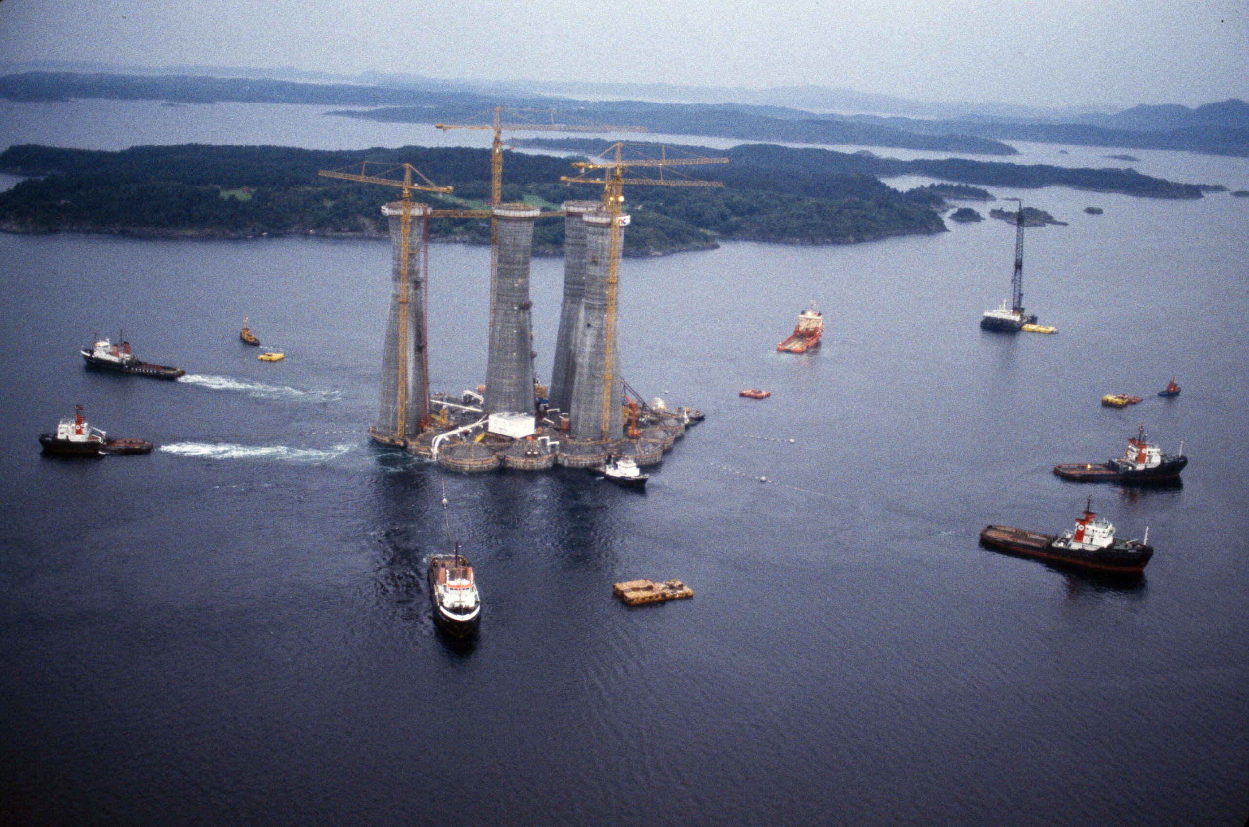
Construction of the A shafts in Gandsfjorden

Two weeks after the bottom cells were launched, on 19 May 1984, work began on building the structure upward. As with other Condeep platforms, this was done using slipforming, a continuous vertical casting process where wet concrete is poured layer by layer—somewhat similar to how a 3D printer operates today.
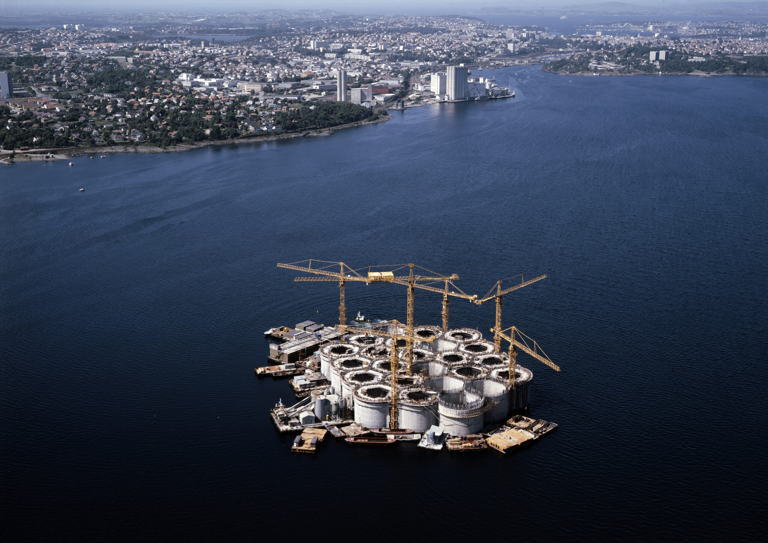
The process was driven by 1,400 hydraulic jacks that lifted the formwork—the structure holding the concrete in place—at a rate of up to six centimeters per hour. The structure was gradually submerged into the fjord as the casting continued upwards. Once the storage cells were completed and sealed at a height of 70 meters, work began on the four 90-meter-tall shafts that would support the platform deck.
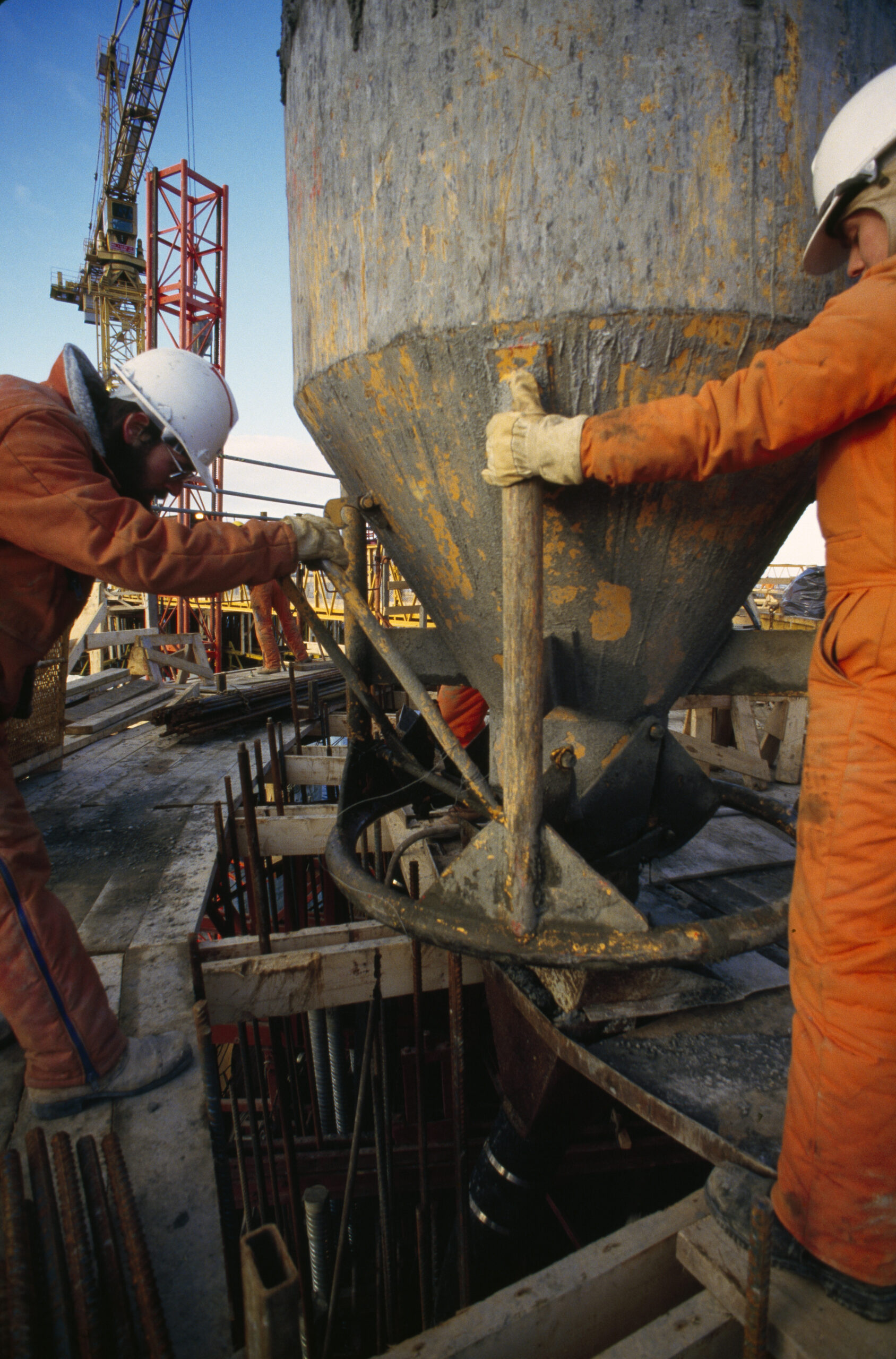
The actual casting process, including manually transporting cement in wheelbarrows, was highly labor-intensive but could largely rely on unskilled workers, such as students. Since much of the work took place in summer, “the slip” became a popular seasonal job.[REMOVE]Fotnote: Statoil. (1990, november). Gullfaks – glimt fra historien om et helnorsk oljefelt. Den norske stats oljeselskap a.s. Stavanger. Side 60-61 https://www.nb.no/items/4f4ceb82f9be24c64834e1a04a0a7ca1?page=0&searchText=helnorsk At its peak, nearly 1,600 workers were involved in building the Gullfaks A substructure.[REMOVE]Fotnote: Hagland, J. (1983, 3. februar). Stavanger Aftenblad, s. 20. At the same time, reinforcement bars were installed to stabilize the structure and ensure it could withstand the pressure at a depth of 130 meters and support the weight of the platform deck.
Building while designing
Detailed engineering continued alongside the construction of the substructure, meaning that a complete plan for every aspect was not finalized beforehand. As a result, construction proceeded with a certain element of “figuring things out as we go.”
Construction manager Kolbjørn Næsje compared the process to pouring a basement before knowing what the roof would look like, as he explained in an interview with Statoil’s internal newspaper Status[REMOVE]Fotnote: Statoil. (1983). Statoil (Vol. 5, Nr. 3, s. 17).
A four-shaft T-formation
The construction of the Gullfaks A concrete substructure followed a familiar pattern. However, unlike previous platforms, Gullfaks A would have four shafts instead of three.
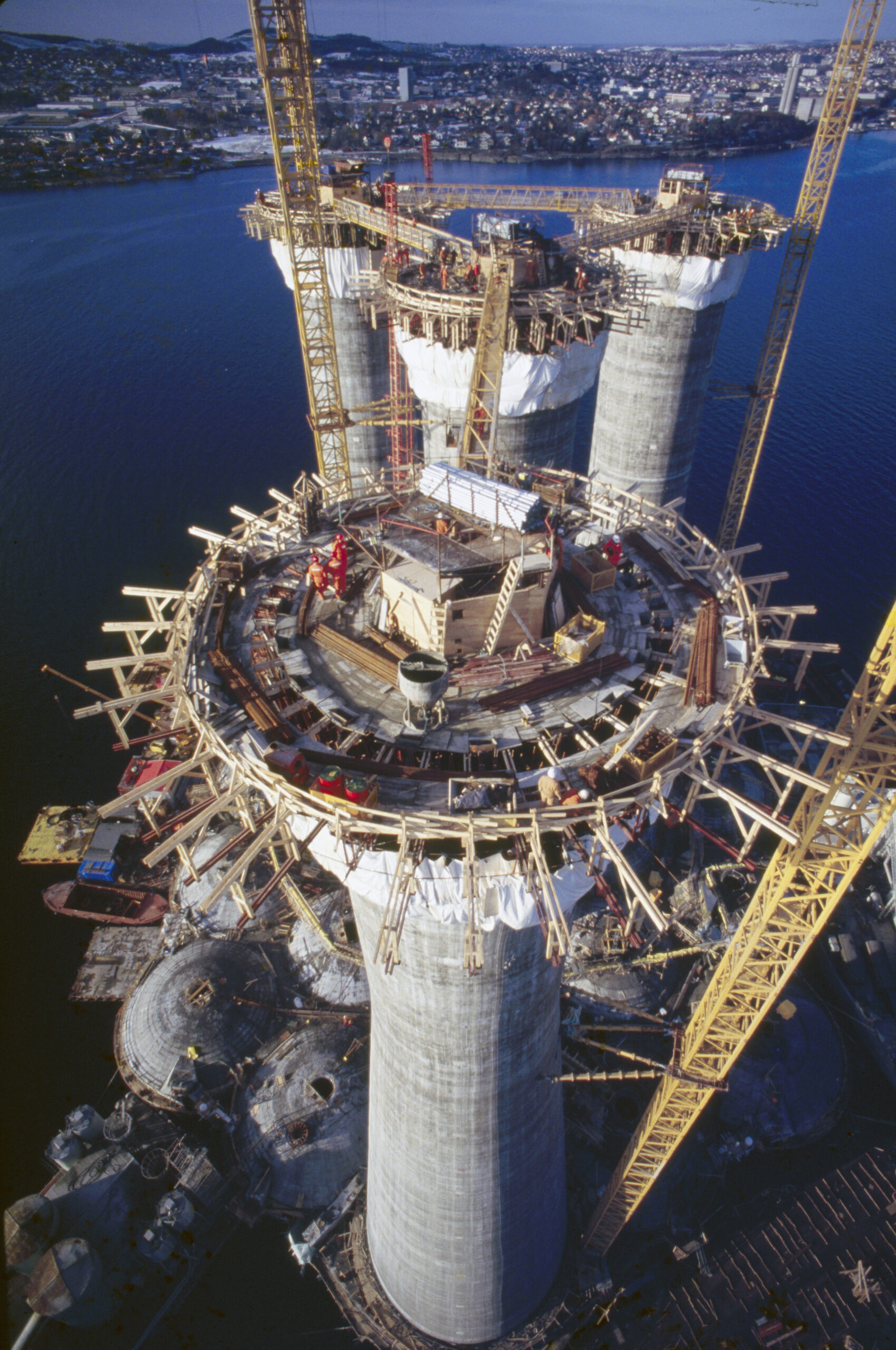
For safety reasons, the platform deck was designed with a greater distance between the drilling area and the living quarters than on earlier platforms, which necessitated the addition of a fourth shaft in the center.
This design affected the layout of the storage cells and the base of the shafts. The shafts were arranged in a T-formation, with two parallel drilling shafts located on the north and south sides beneath the eastern part of the platform, the utility shaft in the center, and the seawater shaft furthest west, beneath the living quarters.
The unique layout required one of the shafts to be built as an extension of one of the storage cells. This cell had to be specially reinforced to ensure stability.[REMOVE]Fotnote: Statoil. (1990, november). Gullfaks – glimt fra historien om et helnorsk oljefelt. Den norske stats oljeselskap a.s. Stavanger. Side 42-47 https://www.nb.no/items/4f4ceb82f9be24c64834e1a04a0a7ca1?page=0&searchText=helnorsk
Concrete failure during construction
During this reinforcement process, an accident occurred. On September 11, 1984, Norwegian Contractors (NC) was working on a concrete plate designed to strengthen the connection between the seawater shaft (west, beneath the living quarters) and the surrounding cells. Before the concrete had set, the plate collapsed, causing 250 cubic meters of concrete to spill into one of the storage cells.
No one was injured or killed, and the platform sustained less damage than one might expect. However, the incident resulted in costs of several million kroner.[REMOVE]Fotnote: Sletten. S. (13.september 1984) Betong-ras på Gullfaks. Stavanger Aftenblad. S. 7
Coordinated steel deliveries
The construction of a Condeep substructure required a large amount of steel, and Gullfaks A was no exception.
For the first time, Norsk Jernverk in Mo i Rana was directly involved in an oil project by signing a contract with the license holders rather than with subcontractors. Norsk Jernverk supplied 5,000 tons of steel beams for the platform. Coordinating deliveries helped improve supply chain control. In total, 28,000 tons of reinforcement steel were used in the platform—equivalent to the weight of four Eiffel Towers.[REMOVE]Fotnote: Statoil. (1990, november). Gullfaks – glimt fra historien om et helnorsk oljefelt. Den norske stats oljeselskap a.s. Stavanger. Side 42-47 https://www.nb.no/items/4f4ceb82f9be24c64834e1a04a0a7ca1?page=0&searchText=helnorsk
For the first time, stainless steel was also used in many of the pipes embedded in the concrete, increasing the durability of critical platform components. At the time, the platform’s expected lifespan was estimated at around 30 years.[REMOVE]Fotnote: Statoil. (1990, november). Gullfaks – glimt fra historien om et helnorsk oljefelt. Den norske stats oljeselskap a.s. Stavanger. Side 42-47 https://www.nb.no/items/4f4ceb82f9be24c64834e1a04a0a7ca1?page=0&searchText=helnorsk
Mechanical outfitting
In the autumn of 1982, Moss Rosenberg Verft was awarded the contract to install mechanical equipment in the concrete structure. This work was carried out partly in parallel with the construction of the substructure and would continue until November 24, 1985.[REMOVE]Fotnote: Risholm, T. (1985, 30. november). God fortjeneste på Gullfaks-skaftet. Stavanger Aftenblad, s. 6.
The shafts contain large amounts of mechanical equipment, including pumps, pipes, meters, and an elevator system. Oil produced on Gullfaks A is transported through the utility shaft before being sent to the storage cells, while gas flows through the same shaft before being transferred to the Statpipe pipeline system. The shaft structure consists of multiple levels, each with different functions.
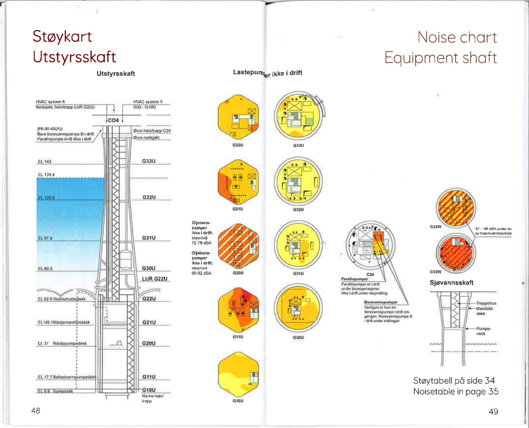
The 48 wells on Gullfaks A all pass through one of the drilling shafts, while the seawater shaft houses pumps and equipment to remove salt from seawater. In other words, the shafts are not just hollow concrete structures. Rosenberg Verft’s job was to install all the equipment needed to make them fully operational.
At a time when the shipbuilding industry was in decline, this contract was crucial for Rosenberg Verft. It gave the yard better prospects than most of its competitors.[REMOVE]Fotnote: Tagesen, D., & Eide, L. (1982, 17. november). Hardt for verft også i Rogaland. Stavanger Aftenblad, s. 27. The final cost reached NOK 780 million (1985 value) and accounted for a total of 1,100 man-years of work. At peak activity, 500 employees were working on the project simultaneously.[REMOVE]Fotnote: Risholm, T. (1985, 30. november). God fortjeneste på Gullfaks-skaftet. Stavanger Aftenblad, s. 6.
The geographic proximity to Norwegian Contractors’ site in Hinnavågen was a key competitive advantage. The shaft outfitting contract was particularly significant because it positioned Rosenberg Verft strongly for the upcoming competition to build the deck—a significantly larger contract than the shaft outfitting. However, the yard did not win the deck contract for Gullfaks A. [REMOVE]Fotnote: Nerheim, G., Jøssang, L. G., & Utne, B. S. (1995). I vekst og forandring: Rosenberg Verft 100 år 1896–1996 (s. 413). Kværner Rosenberg a.s.
Tow-out to Digernessundet
On August 16, 1985, the substructure was ready for departure from Gandsfjorden to Digernessundet near Stord, where it would be mated with the deck. The structure weighed 630,000 tons and was handled by nine tugboats.[REMOVE]Fotnote: Olsen, M. (1985, 16. august). Gullfaks A i oppbrudd. Stavanger Aftenblad, s. 7. In Digernessundet, the substructure would remain for about six months until the deck was ready.
Gullpipe plan abandonedConstruction begins in dry dock