
Testing, testing

The 1980s were a heyday for engineering and display models, but other kinds of models were also made. These were not built to visualize complex drawings or help people grasp what a platform was.
These other models were simpler, designed to test things like wind and wave conditions, load capacity and centre of gravity, and how deep a platform could be set in the water during tow-out.
Model testing was not new at the time; it was what you did with new types of structures. Even today, with widespread access to software and IT technology, testing is still necessary for new structural concepts. Software can help us test what we already know, but the data these tools rely on is grounded in model testing.[REMOVE]Fotnote: Sverre Steen et al., “Stort behov for modelltesting i basseng,” Aktuelt frå NTNU, June 10, 2024, https://www.ntnu.no/norskhavteknologisenter/stort-behov-for-modelltesting-i-basseng, accessed November 25, 2025.
Three test campaigns were described in Statoil’s magazine in 1982, 1983, and 1988. What they shared was that each involved something new that had not been tested before – or where more could be learned. First up were the wind conditions on Gullfaks A.
Eerie storms
At the model shop of the National Maritime Institute on the outskirts of London, a model was built to wind-test the platform. The purpose was to see how wind conditions affected the model, for example the impact on helicopters landing and taking off, as well as issues related to ventilation.[REMOVE]Fotnote: Thorvald Buch Hansen, “Kunstig storm for miniplattformen,” Statoil, 1982, vol. 4, no. 2, 4–8.
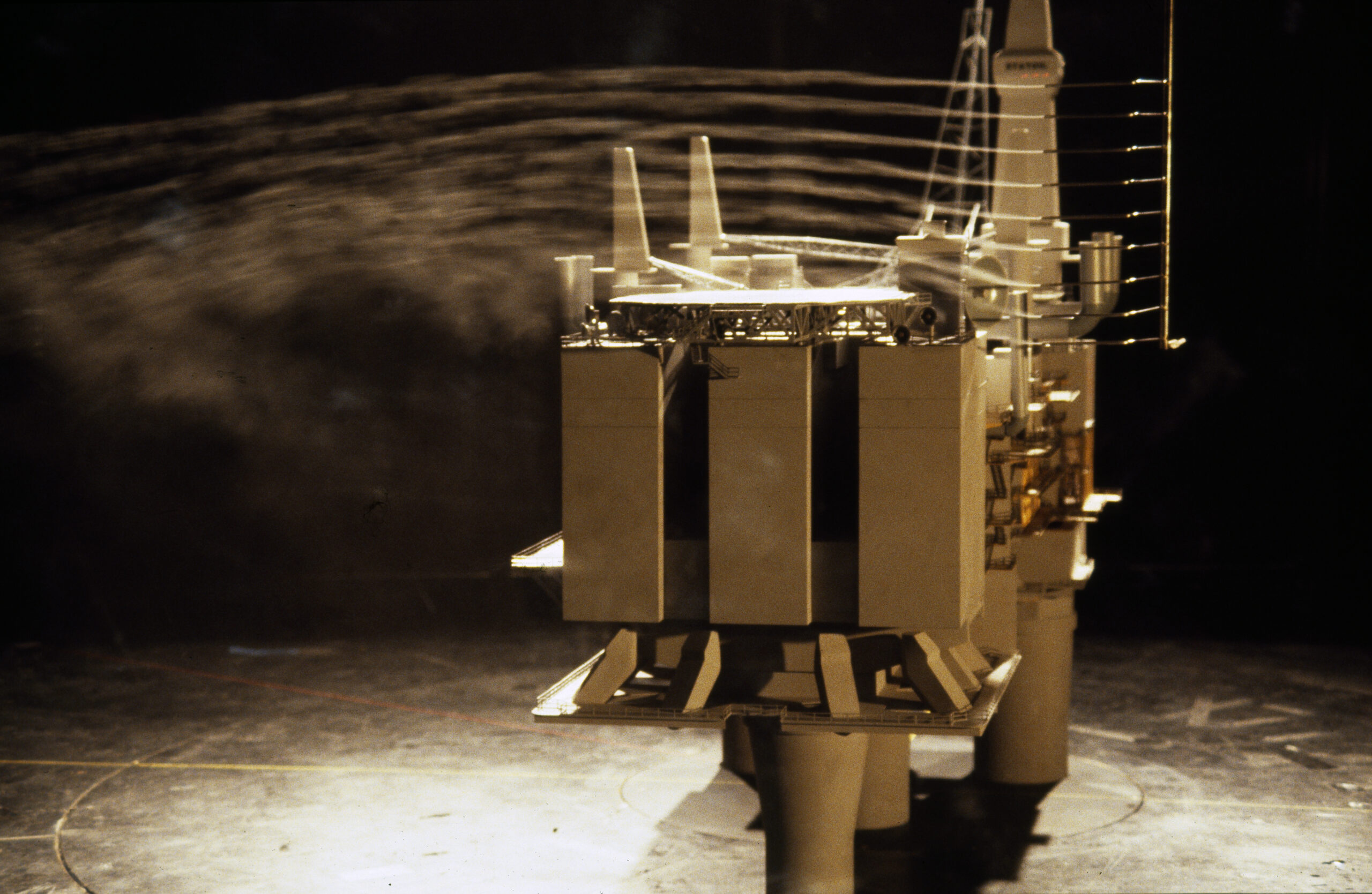
The Gullfaks A model made in 1983 was – compared with other models from the same period – a straightforward build in wood and plastic. It was then painted grey.
The color was no accident. Along with the artificial wind, vaporized oil was released. This “smoke” showed up best against the gray model.
The model was exposed to winds of varying strength. At the institute, it was possible to simulate anything from a fresh breeze to well beyond hurricane force. The model was mounted on a turntable so wind from different directions could be measured.
Measurements were recorded and processed by a computer.
Vic Quincey was responsible for the wind-tunnel tests. He noted they were especially looking at two things: how the wind affected the platform, and how the platform affected the wind. The results would influence how Gullfaks A ultimately looked. The goal was a platform that was safe and pleasant to work on.[REMOVE]Fotnote: Hansen, “Kunstig storm,” 4–8.
The loading buoy had a different goal.
Goal: A simple loading buoy
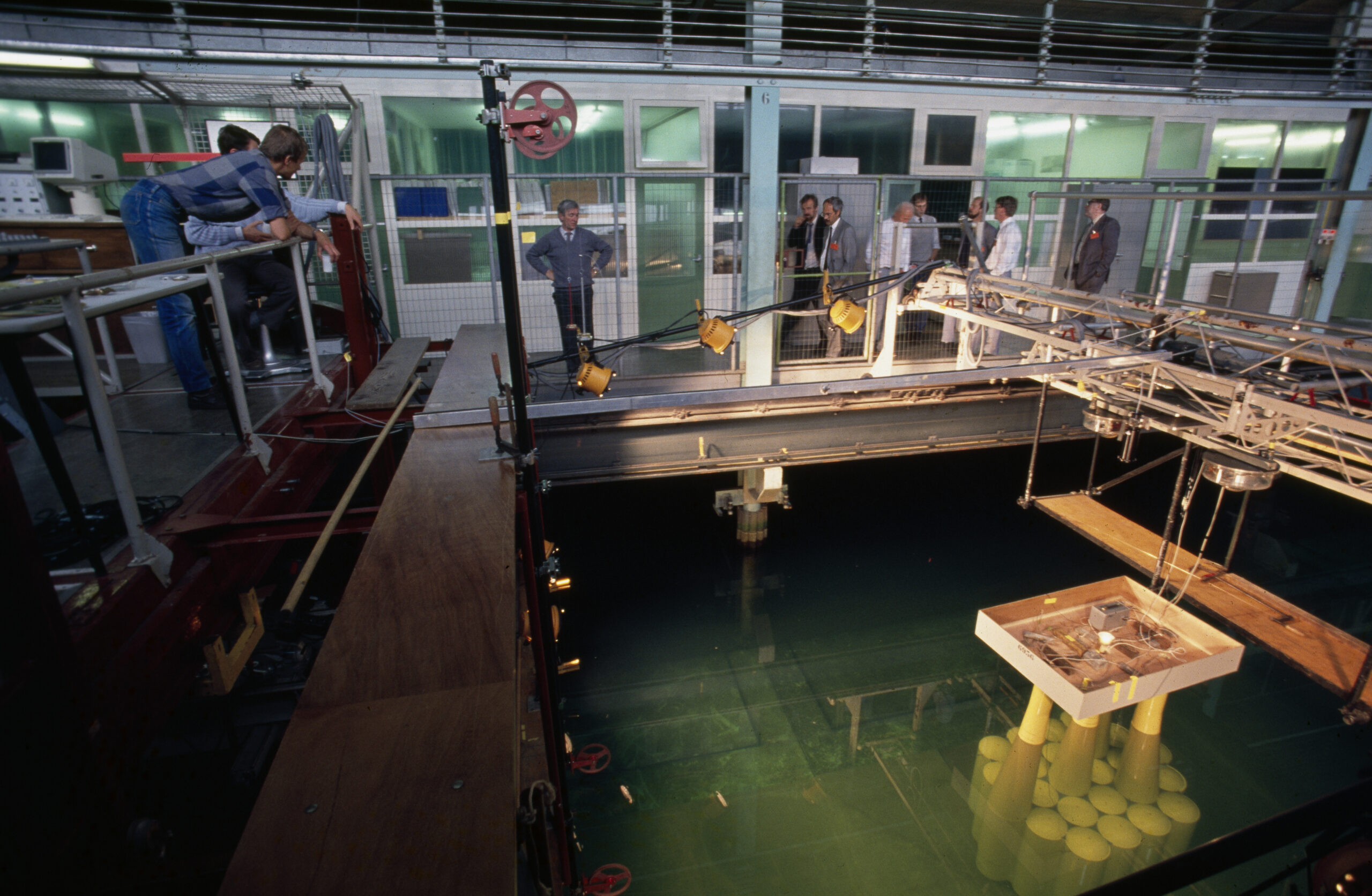
Tom Grove Knutsen and Jan Ingar Knudsen—both attached to Statoil’s Gullfaks A project—explained that the aim of such a test was to confirm that theoretical calculations matched reality. They took part when the loading buoy model was tested in the ocean basin in Trondheim in the autumn of 1983. They added that any surprises were far better at model stage than after the buoy was built.[REMOVE]Fotnote: Odd Jan Lange, “Ny lastebøye i grundig test,” Statoil, 1983, vol. 5, no. 4, 32.
The loading buoy designed as a hub for offloading crude from the Gullfaks field was in many ways similar to comparable buoys, such as those used on the Statfjord field.
Even so, it was decided to run tests on a 1:50 scale model to verify theoretical behavior, things mathematical models do not capture. Some changes had also been made to the Gullfaks buoy compared with the Statfjord buoys.These had to be tested too.
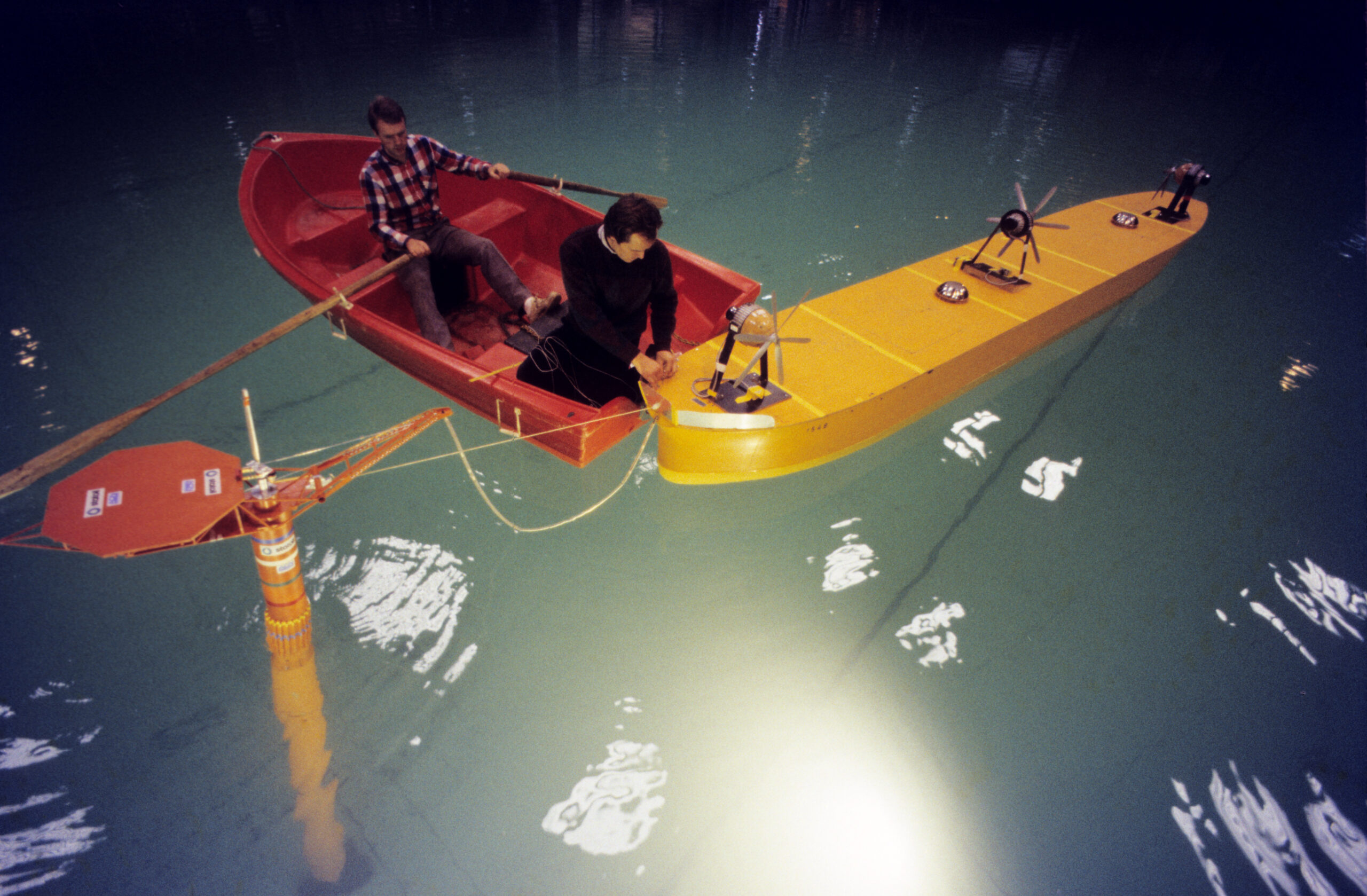
Examples included making the Gullfaks buoy simpler with fewer functions. The aim was to strip out anything unnecessary and costly, both in fabrication and in maintenance. Removing equipment made the buoy lighter, which in turn meant the foundation could also be lighter. How light it could be was worth testing.
The buoy’s helideck was also placed somewhat differently—offset further to the side. How would a less centrally located helideck be affected by wind and wave conditions?
The interaction between the buoy and the shuttle tanker was examined as well, since the tanker would in any case be moored to the buoy during offloading.
A total of 34 tests were carried out. The tests showed that the theoretical calculations were largely correct. No major surprises were uncovered.[REMOVE]Fotnote: Lange, “Ny lastebøye i grundig test,” 34.
Five years later, in 1988, a model of Gullfaks C was built. The following year, what was then the world’s heaviest and tallest platform was to be moved.
How deep can it go?
Statoil wanted Gullfaks C, during tow-out from Stord to the field, to be set as deep in the water as possible. The deeper the draft during tow, the more deck load the platform could carry without becoming top-heavy. And the more load carried during transport, the less would need to be lifted aboard after the platform was set down on the field.
The most obvious limit on how deep the platform could sit was, of course, the water depth along the route from Stord to the field. The Langenuen fjord east of Stord is 215 meters at its deepest. Could the platform still be lowered to 205 meters without risking a grounding?
That would partly depend on how vortex-induced motions around the shafts caused the platform to pitch. Excessive pitching increased the risk of touching bottom. Some of this might be managed by speed. Four speeds, from 0.8 to 2 knots, were tested.
The tests were conducted at Maritime Research Institute Netherlands in Wageningen, where a towing tank long enough for this work was available.
The final outcome is not stated in the 1988 article, beyond noting that the results would determine how much deck load Gullfaks C could take to sea.[REMOVE]Fotnote: “Reisen til havs,” Statoil, 1988, vol. 10, no. 2, 25.
The three major investigations carried out during the 1980s each helped, in their own way, to reduce costs, improve safety, and validate mathematical calculations. Different forms of testing helped avoid the big reefs in the sea – both literally and figuratively.